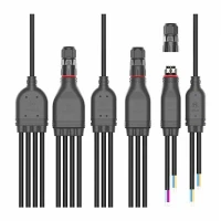
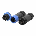
In the realm of electronic and communication systems, splitter connectors play a crucial role in distributing signals efficiently. One of the key performance metrics that engineers and system integrators often look at is the return loss of a splitter connector. As a leading splitter connector supplier, we understand the significance of this parameter and its impact on overall system performance. In this blog post, we will delve into what return loss is, why it matters, and how it relates to our splitter connectors.
Understanding Return Loss
Return loss is a measure of how well a device, in this case, a splitter connector, matches the impedance of the transmission line it is connected to. Impedance is the opposition that a circuit presents to the flow of alternating current (AC). When a signal travels through a transmission line and encounters a splitter connector, some of the signal may be reflected back towards the source instead of being transmitted through the connector. This reflection occurs when there is an impedance mismatch between the transmission line and the connector.
Return loss is expressed in decibels (dB) and is defined as the ratio of the power of the incident signal to the power of the reflected signal. Mathematically, it can be represented as:
[RL = - 20\log_{10}\left(\frac{V_{r}}{V_{i}}\right)]
where (RL) is the return loss in dB, (V_{r}) is the voltage of the reflected signal, and (V_{i}) is the voltage of the incident signal. A higher return loss value indicates less signal reflection and better impedance matching. For example, a return loss of 20 dB means that only 1% of the incident power is reflected back, while 99% is transmitted through the connector.
Why Return Loss Matters
The return loss of a splitter connector has several implications for the performance of an electronic or communication system. Here are some of the key reasons why it matters:
Signal Integrity
Signal reflection can cause distortion and interference in the transmitted signal. When a portion of the signal is reflected back, it can combine with the incident signal, creating standing waves. These standing waves can lead to fluctuations in the signal amplitude and phase, which can degrade the quality of the transmitted data. By minimizing signal reflection through good impedance matching (high return loss), we can ensure better signal integrity and reduce the likelihood of errors in data transmission.


Power Efficiency
Reflected signals represent wasted power. In a system where power consumption is a concern, such as in battery-powered devices or large-scale communication networks, minimizing signal reflection can help improve power efficiency. By reducing the amount of power that is reflected back towards the source, more power can be effectively transmitted through the splitter connector and used by the connected devices.
System Reliability
Poor return loss can also affect the reliability of a system. Over time, the repeated reflection of signals can cause damage to the components in the system, such as the connector itself, the transmission line, and the connected devices. This can lead to premature failure of the system and increased maintenance costs. By ensuring good return loss performance, we can enhance the reliability of the system and reduce the risk of downtime.
Return Loss in Our Splitter Connectors
As a splitter connector supplier, we are committed to providing high-quality products with excellent return loss performance. Our engineers use advanced design and manufacturing techniques to ensure that our connectors have low impedance mismatch and high return loss values.
We offer a wide range of splitter connectors, including the A20 2pin Waterproof Connector, the M15 F Type Waterproof Connector, and the M20 4pin Waterproof Connector. These connectors are designed to meet the diverse needs of our customers in various applications, such as telecommunications, automotive, and industrial automation.
Our connectors are rigorously tested to ensure that they meet or exceed industry standards for return loss. We use state-of-the-art testing equipment to measure the return loss of our connectors at different frequencies and under various operating conditions. This allows us to provide our customers with accurate and reliable performance data for our products.
Factors Affecting Return Loss
Several factors can affect the return loss of a splitter connector. Here are some of the key factors that we take into consideration during the design and manufacturing process:
Connector Design
The design of the connector plays a crucial role in determining its return loss performance. Factors such as the shape and size of the connector, the materials used, and the way the connector is assembled can all affect the impedance matching and signal reflection. Our engineers use advanced simulation tools to optimize the design of our connectors and ensure that they have low impedance mismatch and high return loss values.
Manufacturing Quality
The quality of the manufacturing process also has a significant impact on the return loss of a connector. Any defects or inconsistencies in the manufacturing process, such as poor soldering, misalignment of components, or contamination, can cause impedance mismatches and increase signal reflection. We have strict quality control measures in place to ensure that our connectors are manufactured to the highest standards of quality and reliability.
Operating Conditions
The operating conditions, such as temperature, humidity, and vibration, can also affect the return loss of a connector. Changes in temperature and humidity can cause the materials in the connector to expand or contract, which can lead to changes in the impedance and signal reflection. Vibration can also cause mechanical stress on the connector, which can affect its performance. Our connectors are designed to withstand a wide range of operating conditions and maintain their return loss performance over time.
Measuring Return Loss
Measuring the return loss of a splitter connector is an important step in ensuring its performance. There are several methods and tools available for measuring return loss, including network analyzers, time-domain reflectometers (TDRs), and vector network analyzers (VNAs).
A network analyzer is a commonly used tool for measuring return loss. It works by sending a known signal through the connector and measuring the reflected signal. The analyzer then calculates the return loss based on the ratio of the incident and reflected signals. Network analyzers can provide accurate and detailed information about the return loss performance of a connector at different frequencies.
TDRs are another type of tool that can be used to measure return loss. They work by sending a short pulse of energy through the transmission line and measuring the time it takes for the reflected pulse to return. By analyzing the shape and amplitude of the reflected pulse, TDRs can provide information about the location and magnitude of impedance mismatches in the transmission line and the connector.
VNAs are more advanced versions of network analyzers that can measure both the magnitude and phase of the reflected signal. They are capable of providing more detailed information about the return loss performance of a connector, including the frequency response and the complex impedance.
Conclusion
In conclusion, return loss is a critical parameter that affects the performance of splitter connectors. As a splitter connector supplier, we understand the importance of providing high-quality products with excellent return loss performance. Our connectors are designed and manufactured to meet the diverse needs of our customers in various applications, and we are committed to ensuring their reliability and performance.
If you are interested in learning more about our splitter connectors or have any questions about return loss, please feel free to contact us. We would be happy to discuss your specific requirements and provide you with the information and support you need. Our team of experts is always available to assist you in selecting the right connector for your application and ensuring its optimal performance.
References
- Pozar, D. M. (2011). Microwave Engineering (4th ed.). Wiley.
- Collin, R. E. (2001). Foundations for Microwave Engineering (2nd ed.). Wiley.
- Gupta, K. C., Garg, R., Bahl, I. J., & Bhartia, P. (1996). Microstrip Lines and Slotlines (2nd ed.). Artech House.