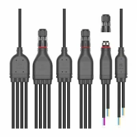
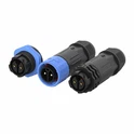
Hey there! As a supplier of Bulk splitter connectors, I've seen firsthand how electromagnetic interference (EMI) can be a real pain in the neck for our customers. EMI can cause all sorts of problems, from signal degradation to complete system failure. That's why I'm here to share some tips on how to reduce the electromagnetic interference of a Bulk splitter connector.
Understanding Electromagnetic Interference
Before we dive into the solutions, let's first understand what electromagnetic interference is. EMI is the disturbance that affects an electrical circuit due to either electromagnetic induction or electromagnetic radiation emitted from an external source. In the case of Bulk splitter connectors, EMI can come from a variety of sources, such as nearby electrical equipment, power lines, or even radio frequency signals.
Shielding
One of the most effective ways to reduce EMI is through shielding. Shielding involves enclosing the Bulk splitter connector in a conductive material that blocks the electromagnetic waves from entering or leaving the connector. There are several types of shielding materials available, including copper, aluminum, and steel.
When choosing a shielding material, it's important to consider its conductivity, thickness, and flexibility. Copper is a popular choice because it has high conductivity and is relatively easy to work with. Aluminum is also a good option because it's lightweight and corrosion-resistant. Steel is a more durable option, but it's also heavier and less flexible.
In addition to the shielding material, it's also important to ensure that the shielding is properly grounded. Grounding helps to divert the electromagnetic energy away from the connector and into the ground, reducing the risk of interference.
Filtering
Another way to reduce EMI is through filtering. Filtering involves using electronic components, such as capacitors, inductors, and resistors, to block or absorb the unwanted electromagnetic frequencies. There are several types of filters available, including low-pass filters, high-pass filters, and band-pass filters.
Low-pass filters allow low-frequency signals to pass through while blocking high-frequency signals. High-pass filters do the opposite, allowing high-frequency signals to pass through while blocking low-frequency signals. Band-pass filters allow a specific range of frequencies to pass through while blocking all other frequencies.
When choosing a filter, it's important to consider its frequency range, attenuation, and insertion loss. The frequency range should match the frequencies of the unwanted electromagnetic signals, while the attenuation should be high enough to effectively block those signals. Insertion loss refers to the amount of signal loss that occurs when the filter is inserted into the circuit, so it's important to choose a filter with low insertion loss.
Layout Design
The layout design of the Bulk splitter connector can also have a significant impact on its EMI performance. When designing the layout, it's important to keep the following tips in mind:
- Minimize the length of the traces: Long traces can act as antennas, picking up and radiating electromagnetic signals. By minimizing the length of the traces, you can reduce the amount of EMI generated by the connector.
- Keep the traces away from each other: Traces that are too close together can cause crosstalk, which is the interference between adjacent traces. By keeping the traces away from each other, you can reduce the risk of crosstalk.
- Use a ground plane: A ground plane is a conductive layer that is used to provide a low-impedance path for the return current. By using a ground plane, you can reduce the electromagnetic radiation generated by the connector.
- Separate the power and signal traces: Power traces can carry high currents and generate electromagnetic fields, which can interfere with the signal traces. By separating the power and signal traces, you can reduce the risk of interference.
Component Selection
The components used in the Bulk splitter connector can also affect its EMI performance. When selecting components, it's important to choose those that are designed to minimize EMI. For example, you can choose components with low electromagnetic radiation, such as surface-mount components or shielded components.
In addition to the components themselves, it's also important to ensure that they are properly installed and connected. Loose connections or improper installation can cause electromagnetic radiation and increase the risk of interference.
Testing and Validation
Once you've implemented the above measures to reduce the EMI of the Bulk splitter connector, it's important to test and validate its performance. Testing can help you to identify any remaining EMI issues and make any necessary adjustments.


There are several types of tests that you can perform, including radiated emissions tests, conducted emissions tests, and immunity tests. Radiated emissions tests measure the amount of electromagnetic radiation emitted by the connector, while conducted emissions tests measure the amount of electromagnetic interference that is conducted through the power and signal lines. Immunity tests measure the connector's ability to withstand electromagnetic interference from external sources.
Conclusion
Reducing the electromagnetic interference of a Bulk splitter connector is essential for ensuring its reliable performance. By implementing the above measures, such as shielding, filtering, layout design, component selection, and testing, you can effectively reduce the EMI and improve the overall performance of the connector.
If you're interested in learning more about our Bulk splitter connectors or have any questions about reducing EMI, please don't hesitate to [contact us for procurement and negotiation]. We're always happy to help!
References
- Electromagnetic Compatibility Engineering by Henry W. Ott
- The Art of Electronics by Paul Horowitz and Winfield Hill
- Electromagnetic Interference and Compatibility by Clayton R. Paul
For more information about our other products, you can check out our T Molding Type Waterproof Connector, Y Type Waterproof Connector, and M15 T Type Waterproof Connector.