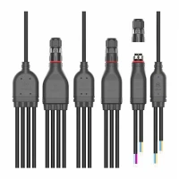
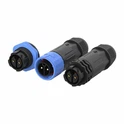
As a shunt connectors supplier, ensuring the quality and performance of our products is of utmost importance. Testing shunt connectors is a critical process that helps us deliver reliable and high - quality components to our customers. In this blog, I will share with you the comprehensive steps and methods on how to test shunt connectors.
I. Visual Inspection
The first step in testing shunt connectors is a thorough visual inspection. This simple yet crucial step can identify many obvious defects.
- Check for Physical Damage: Examine the connector body for any cracks, chips, or dents. These physical damages can compromise the integrity of the connector and lead to electrical or mechanical failures. For example, a crack in the insulation can expose the conductive parts, increasing the risk of short - circuits.
- Verify Pin Alignment: Ensure that all the pins in the connector are properly aligned. Misaligned pins can prevent a proper connection, causing intermittent electrical contact or even complete failure. This is especially important for connectors with multiple pins, such as the M15 T Type Waterproof Connector which requires precise pin alignment for optimal performance.
- Inspect the Surface Finish: A smooth and uniform surface finish is an indication of good manufacturing quality. Look for any signs of uneven plating, oxidation, or contamination on the pins and the connector body. Oxidation on the pins can increase the contact resistance, affecting the electrical conductivity.
II. Electrical Testing
Electrical testing is the core of shunt connector testing, as it directly assesses the connector's ability to conduct electricity effectively.
- Resistance Testing: Use a multimeter to measure the resistance of the shunt connector. The resistance value should be within the specified range provided by the design specifications. A higher - than - normal resistance may indicate poor contact, a damaged conductor, or oxidation on the pins. For example, if the resistance of a Y Type Waterproof Connector is significantly higher than the expected value, it may cause power losses and affect the overall performance of the electrical system.
- Continuity Testing: Continuity testing is used to check if there is a complete electrical path through the connector. Connect the multimeter to the two ends of the connector and set it to the continuity mode. A beep sound indicates that there is a continuous electrical path. This test helps to detect any open circuits, which could be caused by a broken conductor or a loose connection.
- Insulation Resistance Testing: Insulation resistance testing measures the resistance between the conductive parts of the connector and the surrounding insulation. A high insulation resistance is essential to prevent electrical leakage and short - circuits. Use an insulation resistance tester to apply a specified voltage across the insulation and measure the resulting current. The measured insulation resistance should meet the required standards.
III. Mechanical Testing
Mechanical testing evaluates the connector's ability to withstand physical stress and maintain a stable connection over time.
- Insertion and Extraction Force Testing: Use a force gauge to measure the force required to insert and extract the connector. The insertion force should be within a reasonable range to ensure easy installation, while the extraction force should be sufficient to prevent accidental disconnection. Excessive insertion force may indicate a problem with the pin alignment or the mating surfaces, while too low an extraction force can lead to unreliable connections.
- Vibration and Shock Testing: Subject the shunt connector to vibration and shock tests to simulate real - world operating conditions. Vibration can cause loose connections, while shock can damage the internal structure of the connector. Use a vibration table and a shock tester to apply controlled vibrations and shocks to the connector. After the test, perform electrical and visual inspections to check for any damage or changes in performance.
- Torque Testing: For connectors that are secured with screws or bolts, torque testing is necessary to ensure that the proper tightening torque is applied. Over - tightening can damage the connector, while under - tightening can result in a loose connection. Use a torque wrench to apply the specified torque and check for any signs of deformation or damage to the connector.
IV. Environmental Testing
Environmental testing assesses the connector's performance under different environmental conditions, such as temperature, humidity, and moisture.
- Temperature Testing: Place the shunt connector in a temperature - controlled chamber and expose it to a range of temperatures, from low to high. Extreme temperatures can affect the electrical and mechanical properties of the connector. For example, high temperatures can cause the insulation to degrade, while low temperatures can make the connector more brittle. After the temperature test, perform electrical and visual inspections to evaluate the connector's performance.
- Humidity and Moisture Testing: To test the connector's resistance to humidity and moisture, place it in a humidity - controlled chamber or expose it to a water spray. Moisture can cause corrosion and electrical leakage in the connector. After the test, dry the connector and perform electrical and visual inspections. Connectors like the M15 F Type Waterproof Connector are designed to withstand high humidity and moisture, and these tests help to verify their waterproof performance.
V. Conclusion
Testing shunt connectors is a multi - step process that involves visual, electrical, mechanical, and environmental testing. By conducting these tests, we can ensure that our shunt connectors meet the highest quality standards and perform reliably in various applications.


If you are in the market for high - quality shunt connectors, we are here to provide you with the best products and services. Our shunt connectors are rigorously tested to ensure their performance and reliability. We welcome you to contact us for more information and to discuss your specific requirements. We look forward to the opportunity to work with you and provide you with the ideal shunt connector solutions.
References
- "Electrical Connector Handbook" by Paul A. Kovacs
- "Mechanical Design of Electronic Equipment" by Craig R. Barrett
- Industry standards and specifications for shunt connectors